|
Hyspan Barco Ball Joint Applications
Ball joints can be installed to absorb pipe movement in many applications ranging from thermal expansion or contraction of pipe, tank or building settlement, movement resulting from a seismic event, equipment movement such as solar panels and platens, and repetitive motion on bridges, oil platforms and ships. Regardless of the source of the motion, the ability of ball joints to absorb the motion relies on the Off-Set® Method.
The following illustrations are typical installations of ball joints. They are primarily illustrated in one plane; however, ball joints are completely universal allowing motion in all planes including rotation around the centerline. No other method of absorbing pipe motion has this capability.
 |
 |
 |
 |
 |
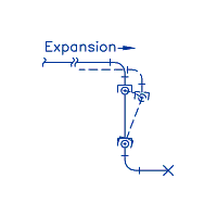
| Figure 1: Two ball joints installed in an offset leg |
|
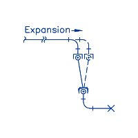
Figure 2: Two ball joints installed in an offset leg with preset or cold spring. |
|
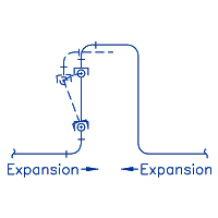
Figure 3: Two ball jointsin a loop. Can also be installed with preset similar to Figure 2.
|
 |
|
 |
|
 |
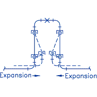
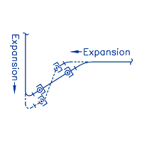
| Figure 4: Four ball joints installed in a loop for high axial motion. |
|
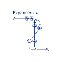
Figure 5: Two ball joints installed in an off-set leg with motion along two axes. |
|
Figure 6: Three ball joint installation with an off-set leg and motion along one axis. |
 |
|
 |
|
 |
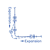
| Figure 7: Three ball joint installation with motion along two axes. |
|
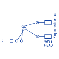
Figure 8: Oil field wellhead installation – ball joints are displaced by twisting or torsion.
(Oil Field Steam Injection)
|
|
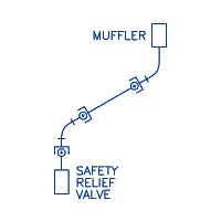
Figure 9: Three ball joints installed in safety relief valve piping. |
Calculation of Thermal Expansion
When materials change temperature they expand or contract in accordance with the equation:
(1)  = =  where where  is the coefficient of thermal expansion, a property of the material, is the coefficient of thermal expansion, a property of the material,  is the change in temperature, and is the change in temperature, and  is the linear dimension that changes temperature. is the linear dimension that changes temperature.
For piping applications the expansion of commonly used piping materials has been tabulated per 100 feet based on an installation temperature of 70°F. Refer to Thermal Expansion of Materials. Using this tabulation,
(1')  = (Tabulated Value) x = (Tabulated Value) x  ÷ 100 where ÷ 100 where  is the thermal expansion in inches, is the thermal expansion in inches,  is the pipe run in feet. is the pipe run in feet.
If the installation temperature is substantially different from 70°F, correct the expansion value by adding or subtracting the expansion from 70°F as appropriate to the installation temperature.
Two Ball Joint Installation
Minimum Two Ball Joint Spacing (L)
The expansion or movement ( ) is determined by calculation of thermal expansion, or it may be given as other system design data such as tank settling or seismic motions. Referring to Figure 10, the minimum length (L) separating the ball joints (rotational center to center) when the joints are installed in the neutral position and the angle ( ) is determined by calculation of thermal expansion, or it may be given as other system design data such as tank settling or seismic motions. Referring to Figure 10, the minimum length (L) separating the ball joints (rotational center to center) when the joints are installed in the neutral position and the angle ( ) is measured from the neutral to the deflected centerline is calculated by the equation: ) is measured from the neutral to the deflected centerline is calculated by the equation:
(2)  = =  (inches) (Figure 10, no preset) (inches) (Figure 10, no preset)
If the expansion or movement is in a single direction, this length can be reduced by installing the ball joints preset or with cold spring. The minimum length, L, is obtained when the preset is equal to one half of the movement ( ). ).
Example 1:
Determine the minimum center to center length for 2 ASME Class Ball Joints (15° total flex angle) installed in piping with 12" of expansion. Referring to Equation (2),  = 12”, = 12”,  = 15°/2 = 7.5°, Sin 7.5° = 0.131 (from table below) = 15°/2 = 7.5°, Sin 7.5° = 0.131 (from table below)  = 12"/0.131 = 91.60". With preset equal to 6" = 12"/0.131 = 91.60". With preset equal to 6"  = 91.60/2 = 45.80" = 91.60/2 = 45.80"
For rough sizing of the off-set length (L), the minimum flex angle for all sizes and configurations of ball joints is 15° total. Referring to Equation (2), the Sine of the half angle, 7.5°, is 0.131. Since 1/0.131 = 7.63 it can be rounded up to 8, L = 8  without preset and L = 4 without preset and L = 4  with preset can be used with conservative results. This is the most conservative approach. If sufficient length is not available use the flex angle for the ball joint configuration selected, and calculate L with Equation (2) with adequate allowances for installation tolerances and additional movement. with preset can be used with conservative results. This is the most conservative approach. If sufficient length is not available use the flex angle for the ball joint configuration selected, and calculate L with Equation (2) with adequate allowances for installation tolerances and additional movement.
Two Ball Joints Installed in an Existing Leg
When ball joints can be installed in an existing off-set leg in the piping the length (L) can be determined and the flex angle ( ) can be calculated for a know deflection ( ) can be calculated for a know deflection ( ) by the following equation. ) by the following equation.
(3)  
Angle
(Degrees) |
 |
Sine |
 |
 |
 |
 |
 |
|
|
1
2
3
4
5
6
6.5
7
7.5
8
|
 |
0.0175
0.0349
0.0523
0.0698
0.0872
0.104
0.113
0.121
0.13
0.139
|
|
|
Angle
(Degrees) |
 |
Sine |
 |
 |
 |
 |
 |
|
|
 8.5 8.5
 9 9
 9.5 9.5
10
10.5
11
11.5
13.5
15
15.5
|
 |
0.148
0.156
0.165
0.174
0.182
0.191
0.199
0.233
0.259
0.267
|
|
|
Angle
(Degrees) |
 |
Sine |
 |
 |
 |
 |
 |
|
|
17
19
20
21
22
23
24
27
30
31
|
 |
0.292
0.326
0.342
0.358
0.375
0.391
0.407
0.345
0.500
0.515
|
|
|
Pipe Displacement (D)
As the ball joints are deflected the off-set length between the parallel pipe runs decreases. In Figures 10 and 11 the lower pipe is anchored and the upper run with the expansion must bend to deflect an amount (D) as illustrated in Figures 10 & 11. The deflection (D) can be calculated by the equation:
(4) D = L –  without preset and without preset and
(5) D = L – 1/2  with preset or D = L – 1/2 with preset or D = L – 1/2  with preset when the preset is equal to with preset when the preset is equal to
the 1/2 of the movement  . .
These equations can be simplified by using the equations:
(6) D =  without preset and without preset and
(7) D =  with preset equal to the 1/2 of the movement with preset equal to the 1/2 of the movement  . .
 is the total displacement or expansion in Equations 4 through 7. is the total displacement or expansion in Equations 4 through 7.
Location of First Restraint
Once the deflection (D) has been determined, the length of pipe to the first restraint (x) can be determined to avoid overstressing the pipe and elbows. Referring to Figures 10 and 11, the minimum length of pipe to the restraint based on the allowable bending stress at the restraint can be calculated by the formula:
(8) x =  (feet) (feet)
d = Outside diameter of the pipe (inches),
E = Modulus of Elasticity (psi) of the material,
S= Allowable Stress (psi) for the pipe material selected.
As an approximation the Modulus of Elasticity, E, can be assumed to be 30 x 10 psi, and a value of 10,000 psi can be used for the Allowable Stress. This value is substantially less the ASME Code allowable; however, it provides a safety factor for stress intensification in the elbows and welds. With these approximations Equation (8) becomes: psi, and a value of 10,000 psi can be used for the Allowable Stress. This value is substantially less the ASME Code allowable; however, it provides a safety factor for stress intensification in the elbows and welds. With these approximations Equation (8) becomes:
(8') x = 5.59   (feet) (feet)
Ball Joint Anchor Forces
The anchor forces resulting from the installation of ball joints result from the seal resistance force that is provided as the Flex Torque (ft.-lbs.) for each nominal size and configuration. Since the outer seal reacts the pressure thrust, the Flex Torque is a function of the system pressure. Charts of Flex Torque are plotted over the pressure range of each ball joint are available on the web page for each configuration. The anchor force (illustrated in Figure 12) can be calculated by the following equation:
Example 2:
Two 10" Type N Style I weld end ball joints with number 11 composition seals (P/N BB-31020-70-11) are to be installed at 70°F in an off-set leg of a 300’ run of steel pipe with operating conditions of 300 psig at 417°F.
The thermal expansion of the pipe is:  = (2.86) x 300÷100 = 8.58" [Equation (1') and Column 2 of Thermal Expansion of Materials 2.86 was extrapolated between 400°F and 450°F]. = (2.86) x 300÷100 = 8.58" [Equation (1') and Column 2 of Thermal Expansion of Materials 2.86 was extrapolated between 400°F and 450°F].
The minimum length of the off-set leg without preset is:  = 8.58" ÷ Sin 8.5° = 57.97" [Equation (2) and Column 3 of Dimensional Data for Type N Style I Ball Joints. The total flex angle is 17° 17/2 = 8.5° Sin 8.5° = 0.148 from tabulation above]. = 8.58" ÷ Sin 8.5° = 57.97" [Equation (2) and Column 3 of Dimensional Data for Type N Style I Ball Joints. The total flex angle is 17° 17/2 = 8.5° Sin 8.5° = 0.148 from tabulation above].
As an alternative the minimum length with preset is equal to 1/2 of  , ,  = 57.97" ÷ 2 = 28.98" [Equation (2’)] = 57.97" ÷ 2 = 28.98" [Equation (2’)]
In order to avoid using the ball joints at the maximum of their capability we recommend rounding these lengths up to 60" and 30". Using Equation (3) the flex angle is:
  = 0.143 = 0.143  8° or 16° total flex angle < 17° design value. 8° or 16° total flex angle < 17° design value.
The pipe displacement, D, is: D =  = 0.61" without preset and using the simplified equation (6) = 0.61" without preset and using the simplified equation (6)
or D = = 0.31" with preset using equation (7). = 0.31" with preset using equation (7).
The minimum distance to the first restraint is: x = 5.59  = 14.31’ (feet) without preset or x = 5.59 = 14.31’ (feet) without preset or x = 5.59  = 10.20’ (feet) with preset using Equation (8') based on an allowable stress of 10,000 psi and a Modulus of Elasticity of 30x10 = 10.20’ (feet) with preset using Equation (8') based on an allowable stress of 10,000 psi and a Modulus of Elasticity of 30x10 psi. Note that the pipe outside diameter is the true diameter (10.75"). Not the nominal size. psi. Note that the pipe outside diameter is the true diameter (10.75"). Not the nominal size.
The force on the anchors resulting from the ball joint seal resistance is: F =  = 2000 lbs. force without preset = 2000 lbs. force without preset
or F =  = 4000 lbs force with preset at 300 psig. Refer to the Type N Style I Ball Joints chart of Flex Torque v. = 4000 lbs force with preset at 300 psig. Refer to the Type N Style I Ball Joints chart of Flex Torque v.
Pressure for the Flex Torque value of 5000 ft.-lbs. Note: This force is a result of the seal resistance only. It does not include the weight of the pipe and media or vertical shear resulting from the pipe bending.
Referring to Figure 12, the length of the off-set leg or the center to center distance between the parallel pipe runs (H) can be calculated.
H = Ball Joint center to center length (L) + Ball Joint Length + 2 Elbow tangent lengths H = 60" + 16.5" (Column 6 of Dimension Data) + 2 x 15" (long radius elbows) = 106.5" without preset and H = 30+16.5 + 2 x 15 = 76.5" with preset.
Three Ball Joint Installations
(10)   (11) (11)   (12) (12)  = =  + + 
Note: Equation (12) is the algebraic sum. In Figure 13  is positive and is positive and  is negative. The length separating the ball joints (L) can be calculated with Equation (2) or (2’), and the Deflection (D) can be calculated from Equations (4), (5), (6) or (7). The location of the third ball joint (L’) can be selected by the designer. When the ball joint (C) is installed directly to the tangent of the elbow (minimum L’), is negative. The length separating the ball joints (L) can be calculated with Equation (2) or (2’), and the Deflection (D) can be calculated from Equations (4), (5), (6) or (7). The location of the third ball joint (L’) can be selected by the designer. When the ball joint (C) is installed directly to the tangent of the elbow (minimum L’),  is maximum and is maximum and  is minimum. is minimum.
Example 3:
Referring to the values used in Example 2 for a 10" Type N Style I ball joint without preset:  = 8.58", L = 60" and D = 0.61". If ball joint (C) is attached directly to the elbow L’ = 15" (tangent length for long radius elbow) + 8.25" (distance to rotational center from Column 5 of Dimensional Data) = 23.25" = 8.58", L = 60" and D = 0.61". If ball joint (C) is attached directly to the elbow L’ = 15" (tangent length for long radius elbow) + 8.25" (distance to rotational center from Column 5 of Dimensional Data) = 23.25"
(10)  = 0.143 = 0.143  8° (11) 8° (11)  = 0.0262 = 0.0262  1.5° 1.5°
(12)  = 8° – 1.5° = 8° – 1.5°  6.5°. A common practice is to locate joint (C) at a distance equal to L i.e. L’ = L. Then 6.5°. A common practice is to locate joint (C) at a distance equal to L i.e. L’ = L. Then
 = 0.010 = 0.010  0.5° and 0.5° and  = 8° - 0.5° = 7.5° = 8° - 0.5° = 7.5°
Example 4:
Three 16’ Type N Style III weld end ball joints with number 21 ductile iron seals (P/N BB-61020-76-21) are to be installed in a piping system. The movement along the horizontal run ( ) is 10” and the vertical movement ( ) is 10” and the vertical movement ( ) is 4". ) is 4".
The total flex angle for P/N BB-61020-76-21 is 21° (Column 3 of Dimensional Data).
To determine the spacing (L) of ball joints A and B without cold spring, Equation (2) can be used for an approximation. Because Equation (2) yields the minimum length based on the horizontal movement only and the maximum flex angle of the ball joint, the spacing must be increased because of the added vertical movement.
(2)  = =  Substituting Sin Substituting Sin  A for Sin A for Sin  with with  A = 21°/2 = 10.5°, Sin A = 21°/2 = 10.5°, Sin  A = 0.182 (from table above), A = 0.182 (from table above),
 = =  = 54.95” ,or using the rough sizing recommended above: L = 8 ( = 54.95” ,or using the rough sizing recommended above: L = 8 ( ) = 8(10) = 80". As a trial L = L’ = 80" ) = 8(10) = 80". As a trial L = L’ = 80"
then (10)  = 0.125 = 0.125  7°, (6) D = 7°, (6) D =  = 0.625" (13) = 0.625" (13)  =0.0422 =0.0422  2.5° 2.5°
(extrapolated from table above – for angles 5° and less the Sine and Tangent are approximately equal  B = 7°+ 2.5° = 9.5° < 10.5° or 1/2 of the total flex angle of the ball joint. The trial layout has yielded satisfactory results – the maximum ball joint angle at joint B is less than the maximum value with a reasonable allowance. B = 7°+ 2.5° = 9.5° < 10.5° or 1/2 of the total flex angle of the ball joint. The trial layout has yielded satisfactory results – the maximum ball joint angle at joint B is less than the maximum value with a reasonable allowance.
If there isn’t sufficient space available to install the ball joints with this layout, they can be installed with cold spring or preset. If the ball joints in Figure 14 are installed with 6" preset on the horizontal run, and we design the center to center distance, L, to be 48" with L’ = L then:
(2’)  = 0.083 = 0.083  A A  5°, (5) D = 48 - 5°, (5) D = 48 -  = 0.166, = 0.166,
(13)  = 0.079, = 0.079,  C C  4.5° (12) 4.5° (12)  B = 5° + 4.5° B = 5° + 4.5°  9.5° 9.5°  10.5° 10.5°
Although there are many different combinations of motions and installations of ball joints, the preceding equations and examples illustrate the two major applications, two and three ball joint installations. From these illustrations the motions of virtually any application can be resolved. If you are confused as I am or need additional assistance please contact the Hyspan Barco representative in your area or Hyspan at websales@hyspan.com .
.

|
|

