Oil Field Steam Injection Well Connections

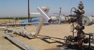
Hyspan Barco Type N Style II, ASME Class and OW1500 ball joints are commonly used to compensate for the thermal expansion of steam injection wells in oil fields. Depending on the well design, the growth can be as great as 1-2 meters (39-79 inches). The recommended ball joint installation for this application is a scissors arrangement shown in the adjacent illustration and photograph below. This arrangement deflects the ball joints in rotation.

There are several important elements of this design:
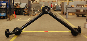
Ball Joint Scissors
Ball Joint Scissors

The orientation of the connections to the well head and supply pipe can be different than the illustration, but the center of rotation of all three ball joints must be in the same plane. For sizes 5" NPS and larger, the scissor linkage must be guided and supported to maintain the in-plane alignment and to react the weight of the linkage.
The supply pipe must be anchored (Main Anchor) as close as possible to the first ball joint. This anchor must be rigid and capable of reacting forces and moments in all planes with the exception (optional) that the supply pipe thermal expansion can be absorbed by allowing the pipe to travel horizontally through the anchor as illustrated. The purpose of the anchor is to maintain the position and configuration of the scissors linkage, react the forces and moments resulting from the internal resistance of the ball joints, and react the forces and moments within the supply piping.
The supply pipe connection and well head connection can be at the same elevation or at different elevations as shown in the illustration. The well head "tree" provides an anchor that reacts the forces and moments resulting from the internal resistance of the scissors. The scissors connection to the "tree" should be as close as possible – avoid any long overhangs that provide a moment arm from the "tree" to the scissors.
The included angle between the legs of the scissors should be approximately 90º at the installed condition, and should not exceed 130º when the well head is fully extended.

As a design aid, the Technical Assistance section includes design recommendations for the scissors linkage design, Leg Length Calculation for Ball Joint Scissor Arrangement. This calculation program provides a convenient method to develop the basic design of a well head connection following the recommendations described above. The complete scissor arrangement including the ball joints, pipe spools, elbows and end connections should fabricated in a shop environment with the end connections accurately located. The ball joints should be installed in the "as received" condition from the factory. They should not be rotated or deflected to assist with the fabrication of the scissors, and the Retainer should not be loosen to facilitate installation. A prefabricated scissors linkage with flanged connections is shown in the adjacent photograph. This completed assembly should be transported to the installation restrained to maintain the configuration. The "yellow" bar shown in the photograph provides this function.

Steam Injection Well

Steam Injection Well

Prefabricated Well Head Scissors connection

Prefabricated Well Head Scissors connection

The Hyspan Barco Ball Joints incorporate design features that are not available in comparable products.

The design includes Inner and Outer Seals which rigidly position the ball, and the outer seal reacts the pressure thrust.
The materials of the seals can be varied to be best suited to the design requirements.
The cavity between the seals is injected with a mixture of graphite flakes and synthetic oil, Grafoil® Flexible Graphite.
Additional graphite packing can be injected through the Injection Ports after the joints are in service without removing the joints. The procedure for injecting packing is described in the Installation and Maintenance Procedures for Type N Style II, ASME Class and OW1500 ball joints.
All Hyspan Barco Ball Joints can be completely disassembled for inspection or maintenance. Sizes through 2" NPS have threaded retainers and larger sizes have flanged retainers as shown in the illustrations.
The removable retainers have the added benefit of allowing precision adjustment of the internal resistance (flex torque) of the ball joint.

Nominal Sizes Through 2 Inch

Nominal Sizes Through 2”

Nominal Sizes 2-1/2” and Over

Nominal Sizes 2-1/2” and Over


Copyright © Hyspan Precision Products, Inc. 2005. All rights reserved.
Hyspan ® is a registered trademark.