 |
|||||||||||||||||||||||||||||||||||||||||||||||||||||||||||||||||||||||||||||||||||||||||||||||||||||||||||||||||||||||||||||||||||||||||||||||||||||||||||||||||||||||||||||||||||||||||||||||||||||||||||||||||||||||||||||||||||||||||||||||||||||||||||||||||||||||||||||||||||||||||||||||||||||||||||||||||||||||||||||||||||||||||||||||||||||||||||||||||||
|
|
|||||||||||||||||||||||||||||||||||||||||||||||||||||||||||||||||||||||||||||||||||||||||||||||||||||||||||||||||||||||||||||||||||||||||||||||||||||||||||||||||||||||||||||||||||||||||||||||||||||||||||||||||||||||||||||||||||||||||||||||||||||||||||||||||||||||||||||||||||||||||||||||||||||||||||||||||||||||||||||||||||||||||||||||||||||||||||||||||||
|
|||||||||||||||||||||||||||||||||||||||||||||||||||||||||||||||||||||||||||||||||||||||||||||||||||||||||||||||||||||||||||||||||||||||||||||||||||||||||||||||||||||||||||||||||||||||||||||||||||||||||||||||||||||||||||||||||||||||||||||||||||||||||||||||||||||||||||||||||||||||||||||||||||||||||||||||||||||||||||||||||||||||||||||||||||||||||||||||||||
| Anchor forces are minimized because the pressure thrust is reacted by the wire braid. | ||
| Anchor forces are minimized because of the inherent high flexibility of the metal hose. | ||
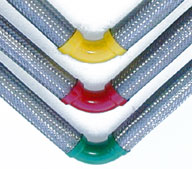
| The "V" configuration allows adjacent piping to be nested to save space. |
||
| V-Flex connectors can absorb in-plane extension and compression, or out of plane lateral offset. |
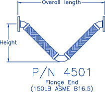
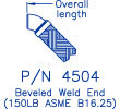
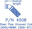
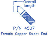
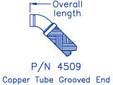
Series 4500 V-Flex Connectors are available as standard products for 1/2" through 4" nominal pipe size with stainless steel braided hose and steel fittings - flanged, weld end or grooved. Copper tube end configurations with bronze hose and braid are available 1/2" through 3" nominal size with female sweat ends or grooved ends. Design conditions are 150 psig and 500ºF with a choice of 2", 3" or 4" of travel.
Thermal Expansion Applications
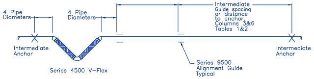
V-Flex connectors can be installed in vertical or horizontal pipe or tube runs as illustrated. The installation must be anchored and properly guided adjacent to the connector and throughout the run. Intermediate guide spacing is given in Tables 1 & 2 below. Refer to Hyspan Series 9500 alignment guides for details on available guides. The Intermediate Anchor must be designed to react a force equal to the connector spring force (Column 3 of Tables 3 & 4). This force is primarily the result of the stiffness of the connector caused by the internal pressure. If the system pressure is less than the 150 psig used for the tabulation, this force can be reduced proportionately.
V-Flex Connector Installed in the Middle of a Run
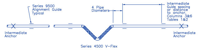
V-Flex Connector Installed Adjacent to an Anchor
Seismic Applications
V-Flex connectors installed for seismic separation require an Intermediate Anchor on each side if the separation that is no greater than the overall length of the V-Flex (Tables 3 & 4) plus four pipe diameters on each side. If the separation is greater, an alignment guide (Series 9500) must be installed within four pipe diameters from the V-Flex. The Intermediate Anchor must be designed to react a force equal to the connector spring force (Column 3 of Tables 3 & 4). This force is primarily the result of the stiffness of the connector caused by the internal pressure. If the system pressure is less than the 150 psig used for the tabulation, this force can be reduced proportionately.
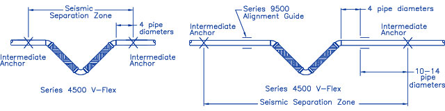
Table 1
Intermediate Alignment Guide Spacing
V-Flex Steel Pipe Connectors
| Nominal Size (NPS) |
Part Number 4501,4504 4505,4508 |
Guide Spacing (Feet) |
Nominal Size (NPS) |
Part Number 4501,4504 4505,4508 |
Guide Spacing (Feet) |
| 1/2 | -V11-2 -V11-3 -V11-4 |
14 | 2 | -V31-2 -V31-3 -V31-4 |
67 |
| 3/4 | -V14-2 -V14-3 -V14-4 |
20 | 2 1/2 | -V35-2 -V35-3 -V35-4 |
98 |
| 1 | -V19-2 -V19-3 -V19-4 |
29 | 3 | -V40-2 -V40-3 -V40-4 |
132 |
| 1 1/4 | -V24-2 -V24-3 -V24-4 |
39 | 4 | -V48-2 -V48-3 -V48-4 |
178 |
| 1 1/2 | -V27-2 -V27-3 -V27-4 |
48 | |||
| 1 | 2 | 3 | 4 | 5 | 6 |
Table 2
Intermediate Alignment Guide Spacing
V-Flex Copper Tube Connectors
| Copper Tube Size |
Part Number 4507,4509 |
Guide Spacing (Feet) |
Copper Tube Size |
Part Number 4507,4509 |
Guide Spacing (Feet) |
| 1/2 | -V08-2 -V08-3 -V08-4 |
5 | 1 1/2 | -V23-2 -V23-3 -V23-4 |
20 |
| 3/4 | -V12-2 -V12-3 -V12-4 |
8 | 2 | -V29-2 -V29-3 -V29-4 |
31 |
| 1 | -V16-2 -V16-3 -V16-4 |
12 | 2 1/2 | -V33-2 -V33-3 -V33-4 |
45 |
| 1 1/4 | -V20-2 -V20-3 -V20-4 |
15 | 3 | -V37-2 -V37-3 -V37-4 |
59 |
| 1 | 2 | 3 | 4 | 5 | 6 |
Note: The alignment guide spacing tabulated in Tables 1 & 2 was calculated in accordance with the recommendations of the Standards of the Expansion Joint Manufacturers Association solely on the basis of the V-Flex spring force. Alignment guides do not provide support for the weight of the system, and it may be necessary to install additional guides for long flexible runs to ensure alignment.
Standard Designs
 |
 |
 |
Materials of Construction
|
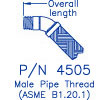 |
Table 3
V-Flex Steel Pipe Connectors
Design Pressure 150 psig Test Pressure 225 psig Design Temperature 500ºF
| P/N 4501 Flanged | P/N 4504 Welded | P/N 4505 Threaded | P/N 4508 Grooved | ||||||||
| Nominal Size (NPS) |
Part Number 4501, 4504 4505, 4508 |
Spring Force (lbs.) |
Height (inches) |
Overall Length (inches) |
Weight (lbs.) |
Overall Length (inches) |
Weight (lbs.) |
Overall Length (inches) |
Weight (lbs.) |
Overall Length (inches) |
Weight (lbs.) |
| 1/2 | -V11-2 -V11-3 -V11-4 |
31 36 40 |
9.69 11.38 12.88 |
21.00 24.38 27.38 |
1 1 1 |
26.00 29.38 32.38 |
2 2 2 |
||||
| 3/4 | -V14-2 -V14-3 -V14-4 |
33 37 42 |
9.94 11.81 13.38 |
20.69 24.44 27.56 |
2 2 2 |
25.69 29.44 32.56 |
2 3 3 |
20.69 24.44 27.56 |
2 2 2 |
||
| 1 | -V19-2 -V19-3 -V19-4 |
37 42 47 |
10.81 12.75 14.44 |
22.81 26.69 30.06 |
3 3 3 |
27.81 31.69 35.06 |
3 4 4 |
22.81 26.69 30.06 |
3 3 3 |
||
| 1 1/4 | -V24-2 -V24-3 -V24-4 |
46 52 59 |
12.50 14.63 16.44 |
26.50 30.75 34.44 |
4 5 5 |
31.50 35.75 39.44 |
5 6 6 |
26.50 30.75 34.44 |
4 5 5 |
||
| 1 1/2 | -V27-2 -V27-3 -V27-4 |
48 56 63 |
13.25 15.44 17.31 |
28.31 32.69 36.44 |
6 7 7 |
35.31 37.69 41.44 |
7 8 9 |
28.31 32.69 36.44 |
6 7 7 |
||
| 2 | -V31-2 -V31-3 -V31-4 |
54 62 70 |
15.06 17.50 19.63 |
33.25 38.13 42.38 |
20 22 23 |
32.75 37.63 41.88 |
10 11 12 |
37.69 42.63 46.88 |
12 13 14 |
32.75 37.63 41.88 |
10 11 12 |
| 2 1/2 | -V35-2 -V35-3 -V35-4 |
57 66 74 |
16.88 19.50 21.81 |
37.56 42.88 47.50 |
31 33 34 |
36.94 42.25 46.88 |
17 19 20 |
43.69 49.00 53.63 |
20 22 24 |
36.94 42.25 46.88 |
17 19 20 |
| 3 | -V40-2 -V40-3 -V40-4 |
62 72 81 |
18.81 21.81 24.25 |
42.19 48.19 53.13 |
39 41 42 |
41.56 47.56 52.50 |
23 25 27 |
48.31 54.31 59.25 |
27 28 31 |
41.56 47.56 52.50 |
23 25 27 |
| 4 | -V48-2 -V48-3 -V48-4 |
83 95 107 |
20.69 23.88 26.56 |
47.50 53.81 59.13 |
61 64 67 |
46.88 53.19 58.50 |
40 43 45 |
53.63 59.69 65.25 |
46 49 51 |
46.88 53.19 58.50 |
40 43 45 |
| 1 | 2 | 3 | 4 | 5 | 6 | 7 | 8 | 9 | 10 | 11 | 12 |
| Note: | (1) The Dash Number in Column 2 indicates the maximum rated travel - dash 2 is 2" axial extension, axial compression or lateral offset. |
| (2) The Spring Force in Column 3 is the force to displace the connector the rated travel at 150 psig. |
 |
 |
Materials of Construction
|
Table 4
V-Flex Copper Tube Connectors
Design Pressure 150 psig Test Pressure 225 psig Design Temperature 500ºF
| P/N 4507 Sweat | P/N 4509 Grooved | ||||||
| Copper Tube Size |
Part Number 4507 4509 |
Spring Force (lbs.) |
Height (inches) |
Overall Length (inches) |
Weight (lbs.) |
Overall Length (inches) |
Weight (lbs.) |
| 1/2 | -V08-2 -V08-3 -V08-4 |
29 33 37 |
10.25 11.81 13.38 |
22.06 25.56 28.63 |
1 1 1 |
39.94 45.25 49.88 |
9 11 12 |
| 3/4 | -V12-2 -V12-3 -V12-4 |
31 34 39 |
12.00 13.75 15.50 |
25.75 29.88 33.38 |
2 2 3 |
41.25 47.63 52.50 |
12 13 15 |
| 1 | -V16-2 -V16-3 -V16-4 |
34 39 44 |
12.63 14.75 16.63 |
28.00 32.25 36.00 |
3 3 4 |
45.13 51.50 56.75 |
16 18 20 |
| 1 1/4 | -V20-2 -V20-3 -V20-4 |
43 48 55 |
14.44 16.75 18.75 |
32.19 36.75 40.88 |
4 5 5 |
||
| 1 1/2 | -V23-2 -V23-3 -V23-4 |
45 52 58 |
15.19 17.56 19.63 |
34.50 39.25 43.25 |
6 7 7 |
||
| 2 | -V29-2 -V29-3 -V29-4 |
50 58 65 |
17.63 20.25 22.63 |
39.94 45.25 49.88 |
9 11 12 |
||
| 2 1/2 | -V33-2 -V33-3 -V33-4 |
53 61 69 |
18.31 21.50 24.00 |
41.25 47.63 52.50 |
12 13 15 |
||
| 3 | -V37-2 -V37-3 -V37-4 |
58 67 75 |
19.88 23.00 25.63 |
45.13 51.50 56.75 |
16 18 20 |
||
| 1 | 2 | 3 | 4 | 5 | 6 | 7 | 8 |
| Note: | (1) The Dash Number in Column 2 indicates the maximum rated travel - dash 2 is 2" axial extension, axial compression or lateral offset. |
| (2) The Spring Force in Column 3 is the force to displace the connector the rated travel at 150 psig. |
Installation Procedure
Application: V-Flex Connectors are designed to absorb thermal or seismic movements as axial motion (direction of pipe or tube centerline) or lateral motion in all planes (perpendicular to the pipe or tube centerline).
Operating Conditions: All V-Flex connectors are designed for 150 psig at 500ºF, and factory tested to 225 psig. Standard connectors are designed for 2", 3" or 4" of axial extension or compression, and 2", 3" or 4" of lateral offset in any plane. Be certain that the system requirements do not exceed the design travel for the connector to be installed.
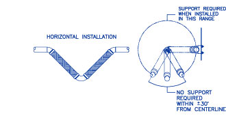
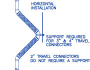
Guides, Supports, Anchors: V-Flex connectors require anchors, guides and supports. Refer to Thermal Expansion Applications (links to Thermal Expansion Applications in V-Flex Text) or Seismic Applications (links to Seismic Applications in V-Flex Text) for the guide and anchor requirements. It may be necessary to support the center elbow of the connector- refer to the illustrations of horizontal and vertical installations.
Flow Direction: The flow can be in either direction.
Shipping Restraints: V-Flex connectors are normally not supplied with shipping restraints. Be certain that the connector is installed
 at the neutral length unless otherwise specified. Refer to the tabulated data,
Tables 3 & 4, for the correct length.
Welding, Brazing & Soldering: V-Flex Connectors must be protected from welding arc strikes, sparks, slag, flux and other debris resulting from the installation of the connector or other activity in the vicinity. Model 4507 requires brazing or soldering for installation. Do not exceed a temperature of 1000ºF and be certain the flux or acid is neutralized.
POST INSTALLATION INSPECTION:
 1) Inspect the connector for damage with special attention to the wire braid.
2) Is the connector at the correct location as specified?
3) Are the anchors and guides correctly installed? Are the guides free to move?
4) Confirm that the connector length is correct.
5) Is the center elbow of the connector supported - if required.
Limited Warranty
V-Flex connectors are manufactured by Hyspan's subsidiary, Universal Metal Hose, who warranty the product - Limited Warranty.
|
|
|
Copyright © Hyspan Precision Products, Inc. 2005. All rights reserved.
|
|