|
 |
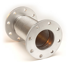 |
Series 2500 Laminated Bellows Expansion Joints
|
 |
Sizes 3" through 18" |
|
|
Laminated 3 ply bellows |
|
|
Austenitic stainless steel and high nickel alloy bellows |
|
|
Maximum flexibility and extended life |
Series 2500 Laminated Bellows Expansion Joints are designed specifically for low pressure applications such as engine exhaust systems, fan connectors, ventilation ducting and air handling systems. The laminated bellows construction permits axial, lateral and angular movements without exerting high spring forces on the system, and the internal damping provided by the laminations limits resonate vibration. Series 2500 Laminated Bellows Expansion Joints are ideal for direct installation on engine exhaust manifolds, turbochargers and fan inlet and exhaust connections. Hyspan Series 2500 Round Expansion Joints are similar designs with single ply bellows that less suitable for vibration applications but ideal for use throughout the ducting and piping. Sizes range from 6" through 48" diameter.
Design Conditions
|
Design Features
|
All Series 2500 Laminated Bellows Expansion Joints are designed for a maximum pressure (including test pressure) of 15 psig and a full vacuum. They are intended for applications such as engine exhaust, fan connections, vents and other very low pressure applications. The design temperature varies with the construction. The materials of construction for standard assemblies are: type 304 stainless steel bellows, van stone ends and flow liners; ASTM A-36 carbon steel plate flanges and angle flanges, and ASTM A-53 standard weight carbon steel pipe weld ends. Optional materials are available including the substitution of stainless steel for flanges and pipe. Recommended design temperatures are 775ºF for Types 2509 & 2511 with carbon steel fittings, 1100ºF for Type 2510 with carbon steel backup flanges and 1250ºF for all configurations if the component parts are stainless steel.
|
Lateral Offset
|
Applications
The lateral offset installation illustrated is a typical application of a Series 2500 Laminated Bellows Expansion Joint installed on an engine exhaust, fan intake or discharge. The high flexibility and internal damping provided by the laminated construction permits absorption of lateral movement from thermal expansion or mechanical motion. Refer to Column 5 of the Design Data for the maximum lateral off-set of each configuration. For applications of this type it is good practice to add Tie Rods to the expansion joint - see Tie Rods below.
Laminated Bellows Expansion Joints can also be installed in axial applications as shown in the axial travel illustration. The maximum Axial Compression and Axial Extension for each configuration is given in Columns 3 & 4 of the Design Data. Most Series 2500 applications do not require the amount of rated axial extension. For these applications the expansion joint can be ordered preset if additional travel is needed. As an example a 3" joint (-040-5) rated for 5" compression factory cold sprung 1" (extended 1") can be rated for 5" compression. The allowable axial extension will be reduced from 2.5" to 1.5".
|
|
Axial Travel
|
 |
|
 |
|
 |
2509 Fixed Flange
|
|
2510 Van Stone Flange
|
|
2511 Weld End
|
Design Data
Type 2509, 2510 & 2511 Laminated Bellows Expansion Joints
Nominal
Size
(NPS)
|
Part Number
2509
2510
2511
|
Axial
Compression
(inches)
|
Axial
Extension
(inches)
|
Lateral
Off-Set
(inches)
|
Axial
Spring Rate
(lb./in.)
|
Lateral
Spring Rate
(lb./in.)
|
Part No. 2509 & 2510
|
Part No. 2511
|
Overall
Length
(inches)
|
Weight
(lbs.)
|
Overall
Length
(inches)
|
Weight
(lbs.)
|
3
|
040-1
040-3
040-5
|
1.25
3.00
5.00
|
0.63
1.50
2.50
|
0.32
1.79
5.13
|
310
159
78
|
795
75
12
|
5.0
9.0
14.0
|
12
|
7.0
11.0
16.0
|
7
|
4
|
048-1
048-3
048-5
|
1.25
3.00
5.13
|
0.63
1.50
2.57
|
0.25
1.40
4.14
|
303
131
78
|
1260
100
20
|
5.0
9.0
14.0
|
16
|
7.0
11.0
16.0
|
8
|
5
|
055-1
055-3
055-5
|
1.25
3.00
5.13
|
0.63
1.50
2.57
|
0.21
1.16
3.41
|
355
153
91
|
2163
172
35
|
5.0
9.0
14.0
|
18
|
7.0
11.0
16.0
|
11
|
6
|
060-1
060-3
060-5
|
1.31
3.00
5.25
|
0.66
1.50
2.63
|
0.18
1.00
2.94
|
378
178
94
|
3261
278
51
|
5.0
9.0
14.0
|
30
|
7.0
11.0
16.0
|
14
|
8
|
067-1
067-3
067-5
|
1.31
3.00
5.31
|
0.66
1.50
2.66
|
0.14
0.78
2.30
|
348
162
94
|
4979
419
84
|
5.0
9.0
14.0
|
40
|
7.0
11.0
16.0
|
18
|
10
|
074-3
074-5
|
3.00
5.31
|
1.50
2.66
|
0.63
1.87
|
191
112
|
752
151
|
9.0
14.0
|
53
|
11.0
16.0
|
30
|
12
|
080-3
080-5
|
3.25
5.56
|
1.63
2.78
|
0.55
1.62
|
134
76
|
776
149
|
9.0
14.0
|
71
|
12.0
17.0
|
35
|
14
|
081-3
081-5
|
3.25
5.63
|
1.63
2.82
|
0.50
1.49
|
125
72
|
873
172
|
9.0
14.0
|
87
|
12.0
17.0
|
45
|
16
|
082-3
082-5
|
3.25
5.63
|
1.63
2.82
|
0.44
1.31
|
131
76
|
1179
233
|
9.0
14.0
|
104
|
12.0
17.0
|
52
|
18
|
083-3
083-5
|
3.25
5.63
|
1.63
2.82
|
0.40
1.17
|
139
81
|
1558
309
|
9.0
14.0
|
109
|
12.0
17.0
|
61
|
1
|
2
|
3
|
4
|
5
|
6
|
7
|
8
|
9
|
10
|
11
|
Tie Rods
Tie rods are available as an option on Series 2500 Laminated Bellows Expansion Joints. They react the pressure thrust in piping and ducting that is not anchored such as the lateral offset application illustrated above. They may also function as Limit Rods. Limit rods do not react the pressure thrust in service but they are designed to react the pressure thrust in the event of an anchor failure. Their main function is to limit the axial extension and compression of the bellows to the rated values. Hyspan normally refers to both tie rods and limit rods as Tie Rods but the factory settings are important - factory settings as Tie Rods do not permit axial extension but limits compression to the rated value of the bellows. Factory settings as Limit Rods will permit axial extension and compression in accordance with the rated travel specified in the Design Data.
Flow Liner
Flow liners or internal sleeves are optional features that are available for all configurations. Liners provide a means of isolating the bellows element from direct contact with the flow and as a result eliminating flow induced vibration, minimizing pressure loss and creating dead air space between the bellows that insulates the bellows. Hyspan installed flow liners follow the recommendations outlined in the Standards of the Expansion Joint Manufacturers Association (EJMA) summarized as follows.
Flow liners are recommended for:
|
|
Gas applications exceeding 4 ft./sec./inch of diameter up to 6" NPS |
|
|
Gas applications exceeding 25 ft./sec. over 6" NPS. |
|
|
Liquid applications exceeding 2 ft./sec./inch of diameter up to 6" NPS. |
|
|
Liquid applications exceeding 10 ft./sec. over 6" NPS. |
|
|
All applications when flow turbulence is generated within 10 diameters from the expansion joint. |
|
|
|
These values must be increased when:
|
|
|
The flow liner length, L, exceeds 18". Multiply the tabulated values by the factor, . . |
|
|
The velocity, V, exceeds 100 ft./sec. Multiply the tabulated values by the factor, . . |
|
|
When the flow is extremely turbulent such as downstream from valves, tees and elbows. Multiply the calculated velocity by 4 to determine if the velocity exceeds 100 ft./sec. |
|
|
If the liner length exceeds 18" and the velocity exceeds 100 ft./sec., apply both factors. |
|
There are special circumstances involving the use of flow liners:
|
|
Standard liners are rigidly attached on the upstream end of the expansion joint and open on the downstream end. If reverse flow conditions exist, the liner thickness must be very heavy gauge or a telescoping design should be used. |
|
Flow Liner
|
|
|
If the expansion joint is installed is a vertical run and the flow is upward, drain holes should be added at the lowest point of the liner to avoid trapped liquid. |
|
|
|
Unless a special oversize bellows design is used, the flow liner will intrude into the pipe or duct flow path. If the expansion joint motion is axial only this intrusion will be minimal, and the liner inside diameter may be comparable to the adjacent pipe or duct. |
|
|
|
If there is lateral or angular motion the gap between the liner outside diameter and the bellows inside diameter must be great enough to allow for this movement - see illustration. |
|
|
|
Connectors designed for axial compression with flow liners must be designed so that the liner does not extent beyond the end of the joint - see illustration. |
|
Ordering Instructions
Refer to the illustrations (2509, 2510 & 2511) above for the configuration required. Refer to the Design Data table for the rated motions, spring rates, lengths and weights.
 Example: Example:
12" nominal diameter
Single fixed flange,
Standard bellows material, 304 stainless steel
Standard Flange Material, A-36 carbon steel
3.0" axial compression, 1.5" extension
Installation Procedure
Operating Conditions: Series 2500 Laminated Bellows Expansion Joints are designed for applications where the pressure including tests does not exceed 15 psig. The design temperature varies with the configuration and materials of construction. Consult the purchase specification for the design temperature and the rated travel of the product purchased. Be certain that the system operating conditions and test conditions do not exceed the rated values.
Guides, Supports, Anchors: Series 2500 Laminated Bellows Expansion Joints are light weight construction. Guides, supports and anchors are important to prevent damage. Refer to the installation drawings for the correct location.
Flow Direction: The flow direction can be from either direction for Series 2500 expansion joints that do not include a flow liner. The flow direction for expansion joints with flow liners is from the fixed (welded) end to the free end and indicated on the exterior. Confirm that the joint is oriented correctly.
Shipping Restraints: External restraints are installed at the factory to ensure installation at the correct length and alignment. They are painted yellow and labeled - Shipping bars, remove after installation. Leave these restraints installed until after the installation of the expansion joint is complete - but they must be removed prior to pressure testing and operating the system. CAUTION: Shipping restraints may be installed by welding. Provide protection for the bellows element from cutting or grinding during removal.
Tie Rods: Tie rods, limit rods and control rods are devices that limit the travel of the expansion joint. They are available as an option on Series 2500 Laminated Bellows Expansion Joints. If they are included, be certain that the installation allows the design movement of the expansion joint.
Post Installation Inspection
|
1. |
Inspect the expansion joint for damage with close attention to the bellows element. |
|
2. |
Is the expansion joint installed at the correct location; are the anchors, guides and supports installed in accordance with the system design? |
|
3. |
Are the guides and supports free to allow the movement of the expansion joint? |
|
4. |
Is the flow direction correct if a flow liner is installed? |
|
5. |
Have the shipping restraints been removed? |
Warranty
The Hyspan Limited Warranty applies to all Series 2500 Laminated Bellows Expansion Joints.
|
|